r7.02.20 Computation of T-stress by extrapolation of displacement field#
Abstract:
The computation of T-stress is implemented for linear, homogeneous and elastic-isotropic materials with plane crack mesh (FEM only). The accuracy of T-stress results obtained by extrapolation of the displacement fieldmethod is clearly improved if the meshing elements are quadratic. It is also highly recommended to use “Barsoum” type elements in the crack tip (elements where the mid-side nodes are located at the quarter of edges).
Implementation of extrapolation method#
The extrapolation displacement method is implemented in the POST_T_Q operator which starts by computing the displacement field on the global structure. Since the definition of T-stress are onlyasymptotically true; extrapolation is restricted to the vicinity of the crack tip limited by a maximum distance \(\mathit{dmax}\) around the crack. \(\mathit{dmax}\) is a parameter of the ABSC_CURV_MAXI operator. In the case of a meshed crack ABSC_CURV_MAXI is optional. If \(\mathit{dmax}\) is not defined in the .comm file, by default it is automatically assigned in POST_T_Q operator as equal to three times the maximum size of the mesh elements connected to the nodes on the crack front. The general principle of T-stress computation is defined as follows:
Loop on the crack tip nodes
Extract the crack tip displacement,
Define the plane normal to crack and the crack tip,
Project the displacement field in \(\theta =+\pi ` and :math:\)theta =-pi ` ,
Calculate thedifference of the displacement value,
The displacement difference is dividedby \(r\) with material multiplicative factor will obtaine and then extrapolate into \(r=0\) . If the solution is perfect, one should obtain a line. Actually, we obtain almost a line with a mesh of the type “Barsoum”.
Accuracy of suggested method#
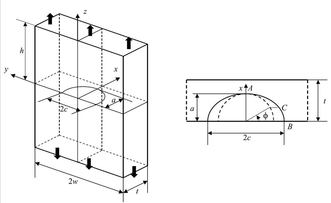
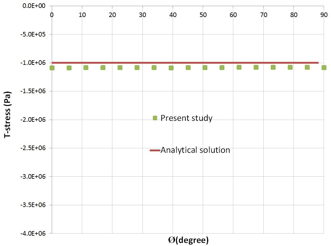
The extrapolation displacement method was validated on the test case (SSS?) , for which analytical solutions are known [3]. This test case, as detailed in (T₁.odt), considers an elliptic crack in a three-dimensional body subject to a tensile load. A cube by size of \((h=w=t=16)\) , containing a horizontal circular crack of radius \(c=a=1\) is considered (see Fig.2). The value of far-field stress, :math:`sigma ` , was prescribes as 1 MPa. Due to symmetry, only one quarter of the elliptical crack is considered. The crack is meshed with fine quadratic mesh type in the vicinity of crack tip. The results are compared with reference solution (see Fig.3).
|
Fig.2Geometric configuration of the testcase shown in half symmetry [3] |
|
Fig.3 T-stress compression |
Conclusion#
The results obtained with extrapolation displacement method are in a good agreement, with less than 5% error compared to the analytical solution of T-stress. It should be noticed that the asymptotic relation of displacements is valid only for \(r\) tending towards 0. Therefore, it is necessary to take care not to choose too large a domain of extrapolation (distance \(\mathit{dmax}\) from operator POST_T_Q of about 4 to 5 elements).
Bibliography#
Novotný, Calculation of T– stress on 3D specimens with crack. Procedia Engineering. 48, 489 – 494. 2012,
S.A. Zahedi, A. Jivkov,Two-parameter fracture characterization of a welded pipe in the presence of residual stresses – Procedia Structural Integrity. 2, 777-784,2016.
Wang, Elastic T-stress solutions for semi-elliptical surface cracks in finite thickness plates. Engineering Fracture Mechanics 70, 731–756, 2003.
Description of the document versions#
Index |
Version Aster |
Auteur(s) or contributeur(s), organisme |
Description of the modifications |
A |
13.4 |
A. Zahedi EDF Energy UKC |
Initial document |